Introduction
For this project, I built a gameport to USB adapter to use my old joystick again!
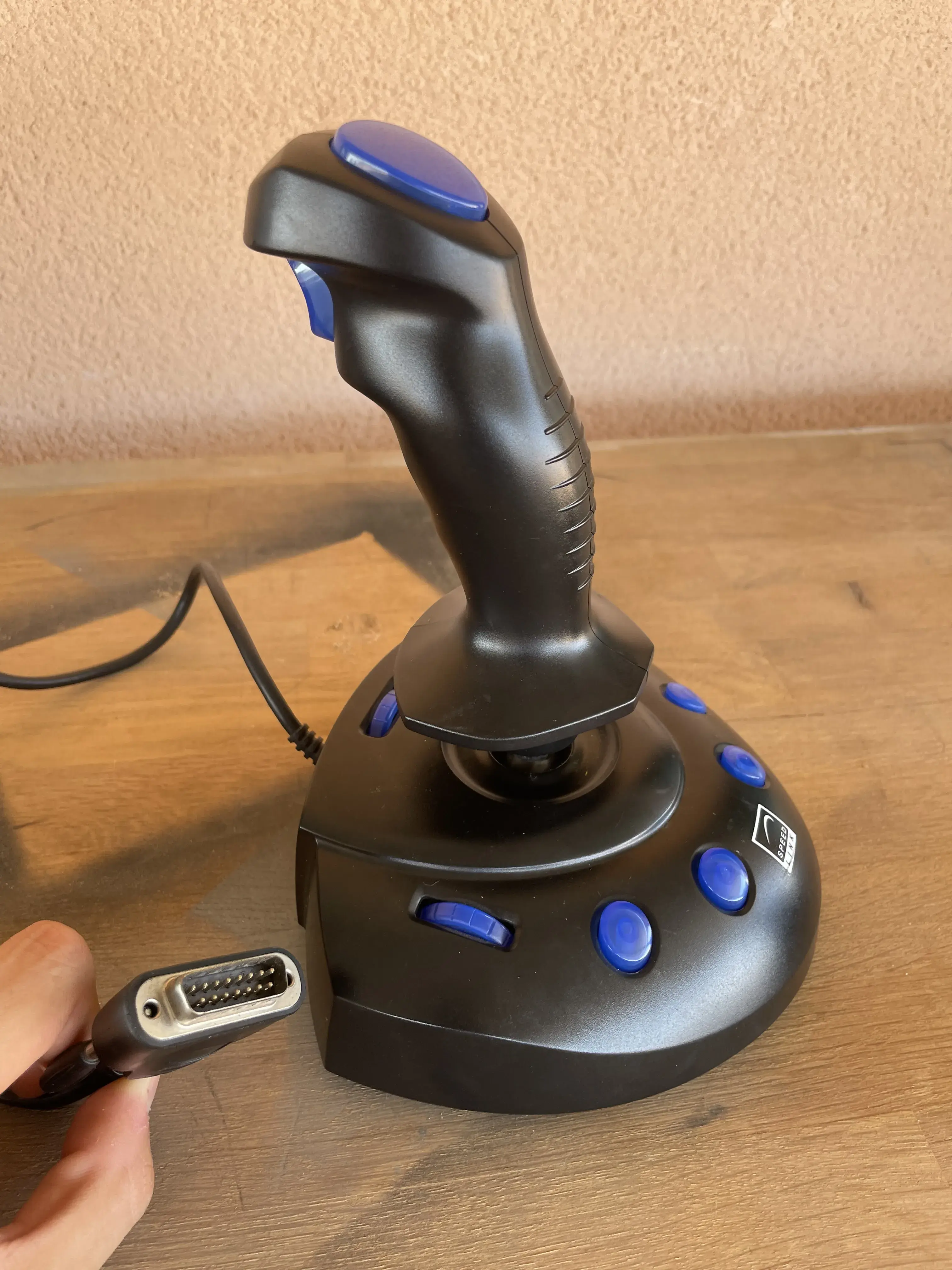
This project started when I stumbled upon a youtube video showcasing a DIY gameport adapter for old PC joysticks when looking for available adapters. Since I have an old joystick lying around, I wanted to use it to play some games!
My initial idea was to buy an adapter, but I did not consider that the options that are worthwhile are all rather expensive in my area, like this rockport one, or are knock offs of the rockport and take a long time to get delivered. Furthermore, the DIY option supports more joysticks than the commercial option. Since I am impatient (and cheap), I decided to scavenge my junk motherboard and parts bin to find the parts to make my own!
What is Gameport?
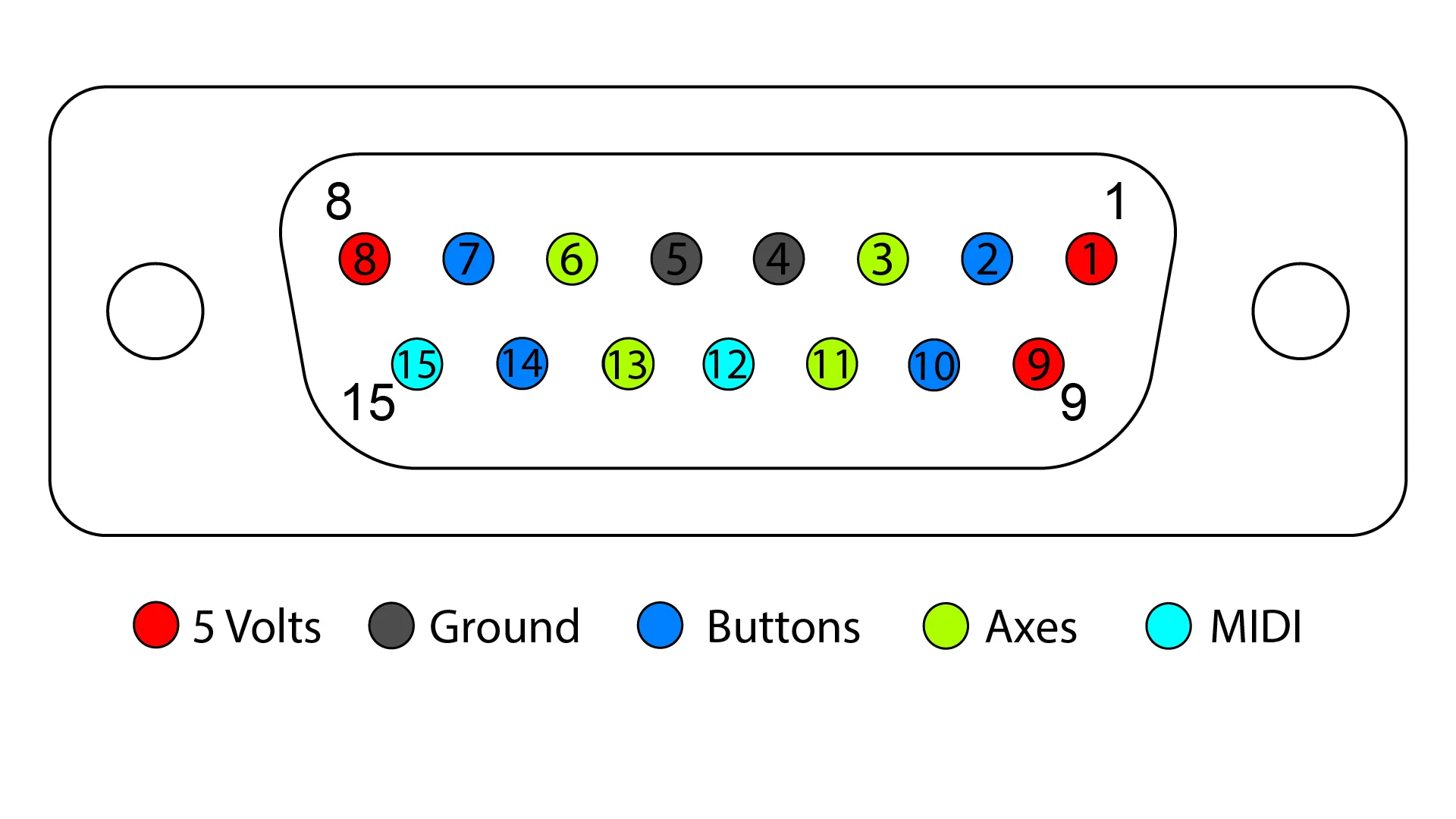
A game port is a 15-pin socket which takes both analog and digital signals from a joystick, as well as +5V, ground and MIDI in/out. These were found on PC systems of the 1980s and 1990s, and were first on their own dedicated expansion cards and later integrated with PC sound cards. I have this IBM PC from 2000 that has it integrated, you can even see the small joystick logo. A layout of the pins is shown in the figure below.
The task of the adapter is to translate these signals into USB protocol messages that perform the same action. For example, if we press jump on button 1 of the joystick, the arduino must send a signal through the USB port that the game running understands as jump. This is all done in the code written by Necroware in his Game port adapter project on Github.
Since the software has been generously already been made, we must only worry about building an adapter that connects everything electrically/in hardware.
Time to make the adapter!
This DIY adapter I will be making is based on the work done by Necroware and their Game port adapter project.
This project provides the code to program an arduino that will allow the adapter to communicate with and translate the input from several different joysticks.
Since this adapter is not commercially available (as of writing this post), and I did not want to spend money on getting the PCBs printed from the files provided by Necroware, I decided that I would use parts lying around my lab to make one myself, and program the arduino using the code found on the Game port adapter project repository.
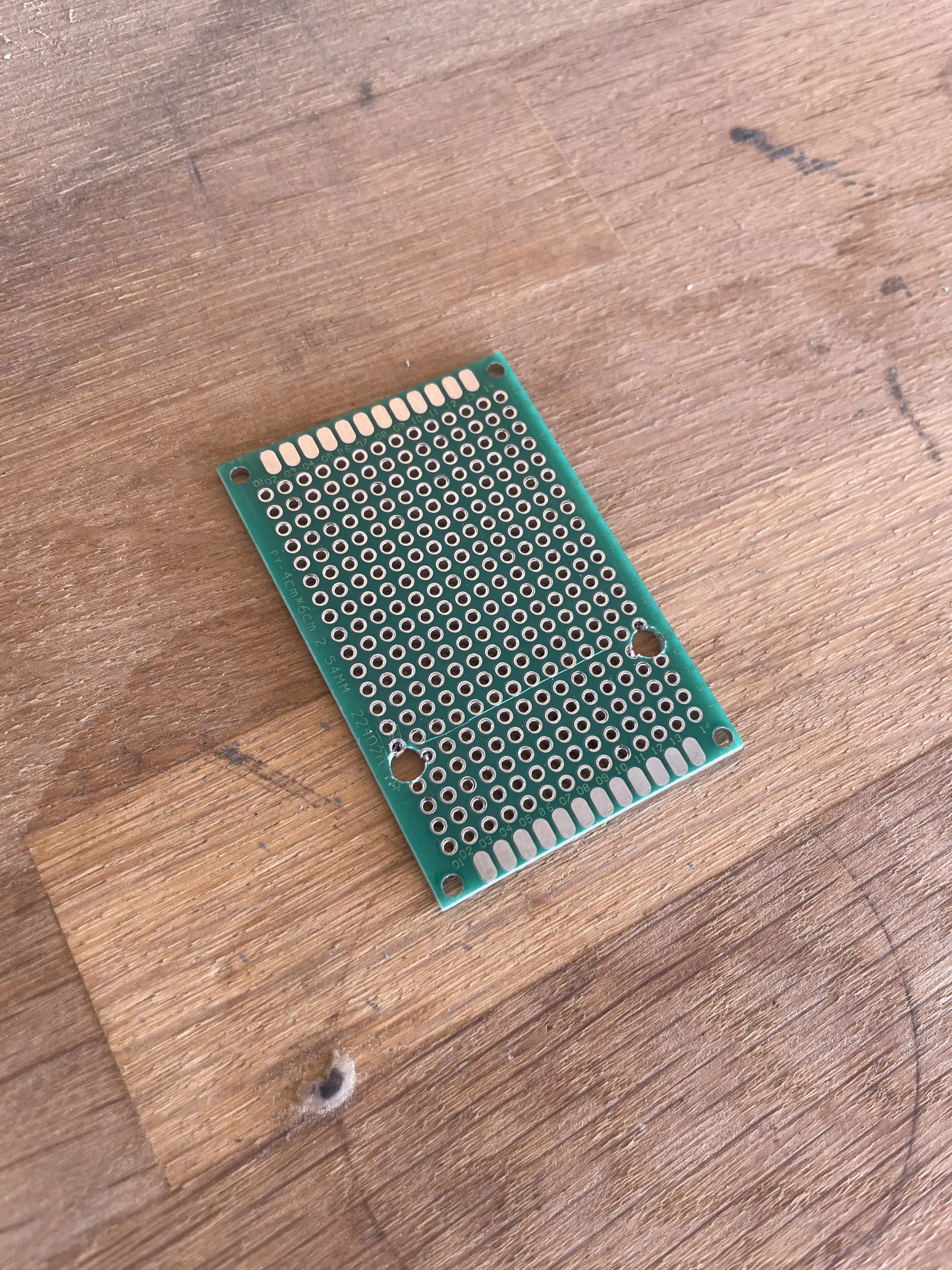
The plan is to solder the parts together on a blank prototyping board by following the electrical schematics, and then programming the arduino with the firmware provided. Luckily, the repository includes all the documents needed to go ahead with this project.
You will need to download/clone this repository since it contains the electrical schematics that are needed to make the connections on the board, and the firmware for programming the arduino. If you instead order the PCB from a PCB manufacturer or make it yourself, you wont need this and the process will be much simpler.
Keep in mind I had most of these things already at hand or replaced them for something suitable, like the fact that I did not have the PCB but used a blank and made the connections myself.
Finding a gameport… port
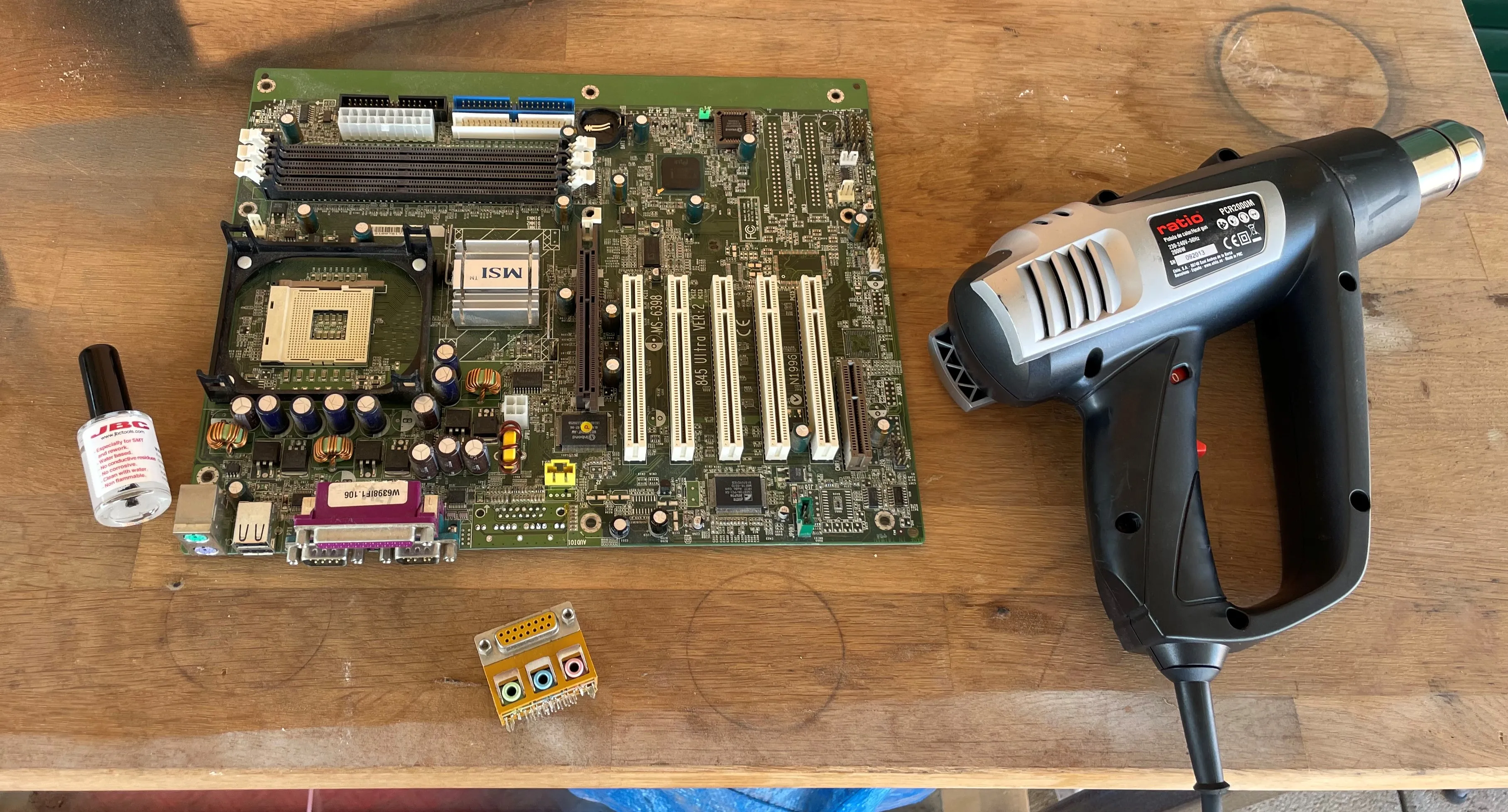
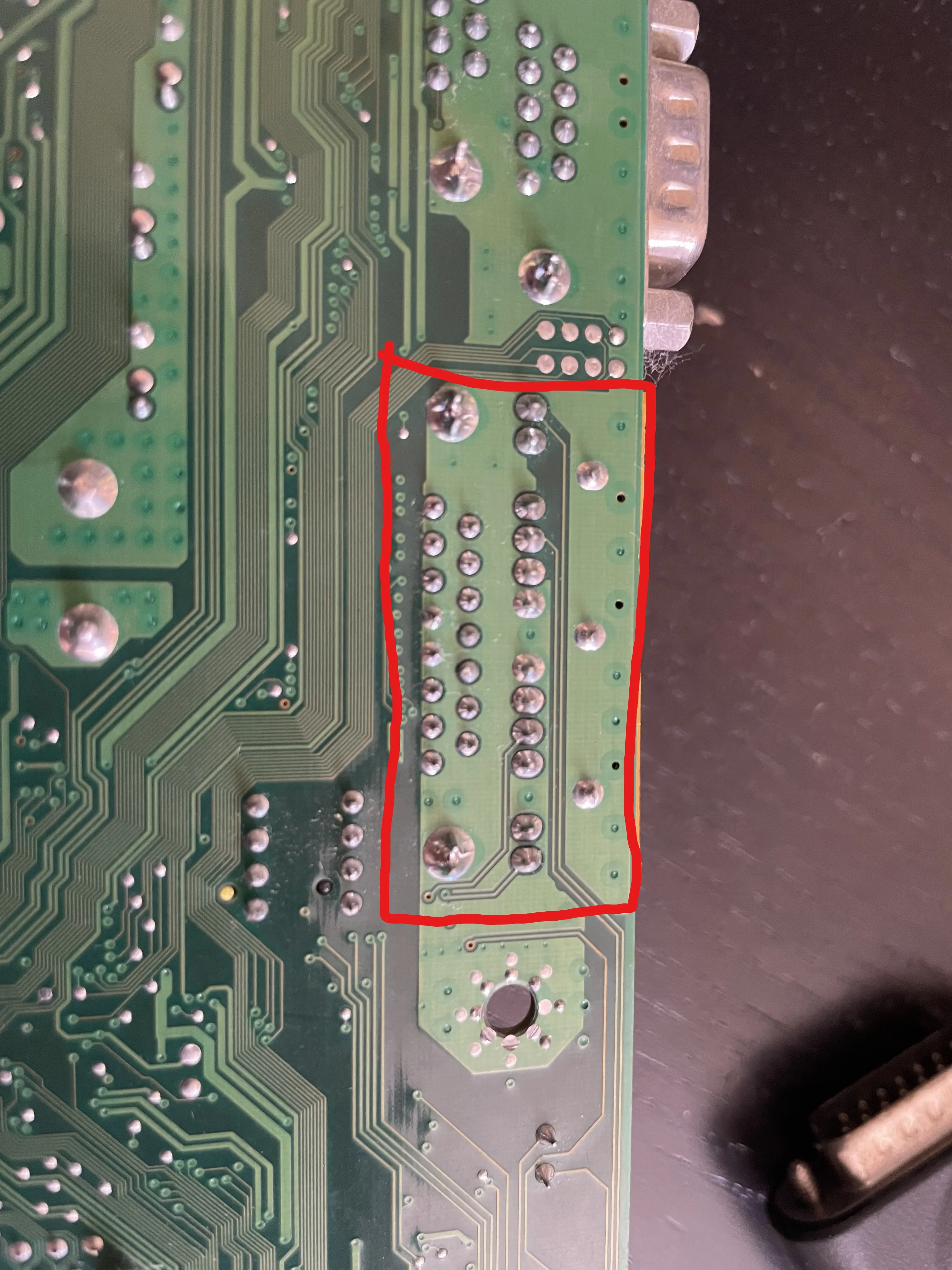
I happened to have an old motherboard with a gameport slot on it, which meant that I needed to get it desoldered.
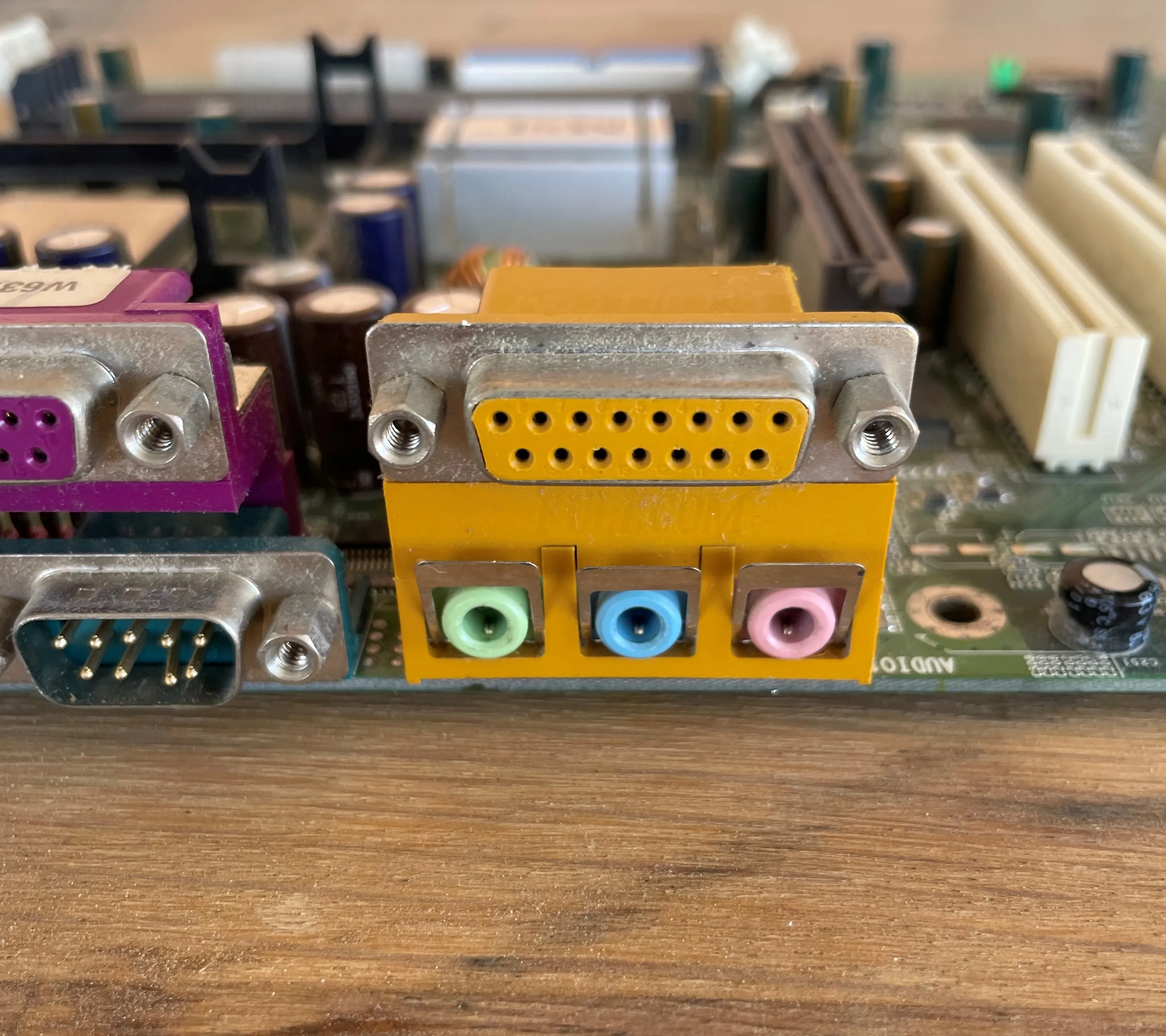
Unfortunately it is a combo port with mic, line out and in ports. Further inspection revealed that these should be able to be separated once the whole connector is desoldered. I used some flux on the back of the board, first removed the 2 structural pins on the sides, with a soldering iron and a desoldering pump, and then used hot air to get the rest of the connector out.
Next step was separating the combo port into its individual components, so I removed the jackscrews from the connector (the threads where you screw into when plugging the connector) and used some force to get the connector apart.
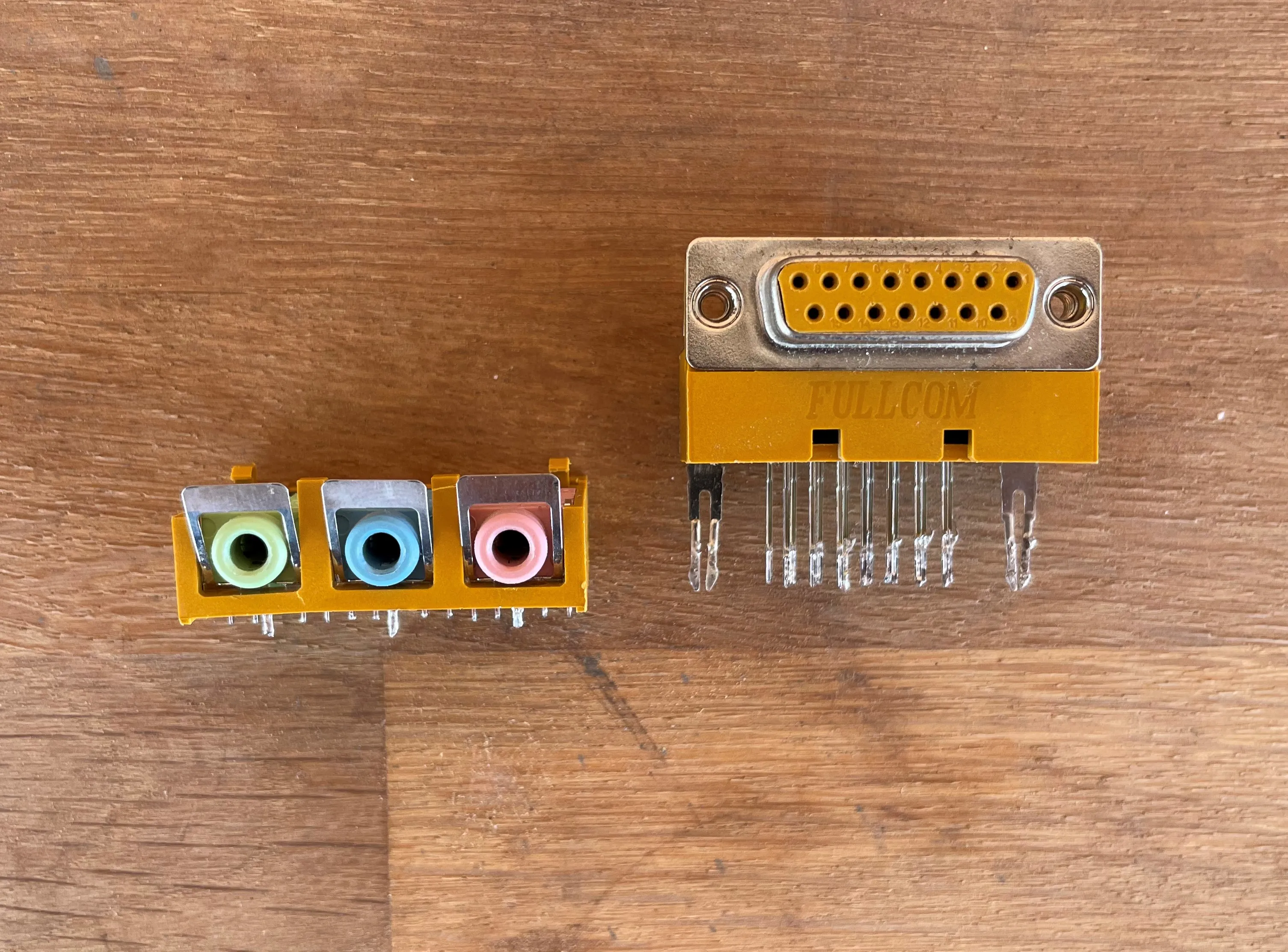
Now that they are separated, I can use the top part for the adapter. The pins on both rows were not aligned, and since I am using an off the shelf PCB board that I had at hand, some of the pins needed to be bent slightly. This was not an issue since the pins are long and very pliable, so I bent them to shape and slotted the connector into the PCB.
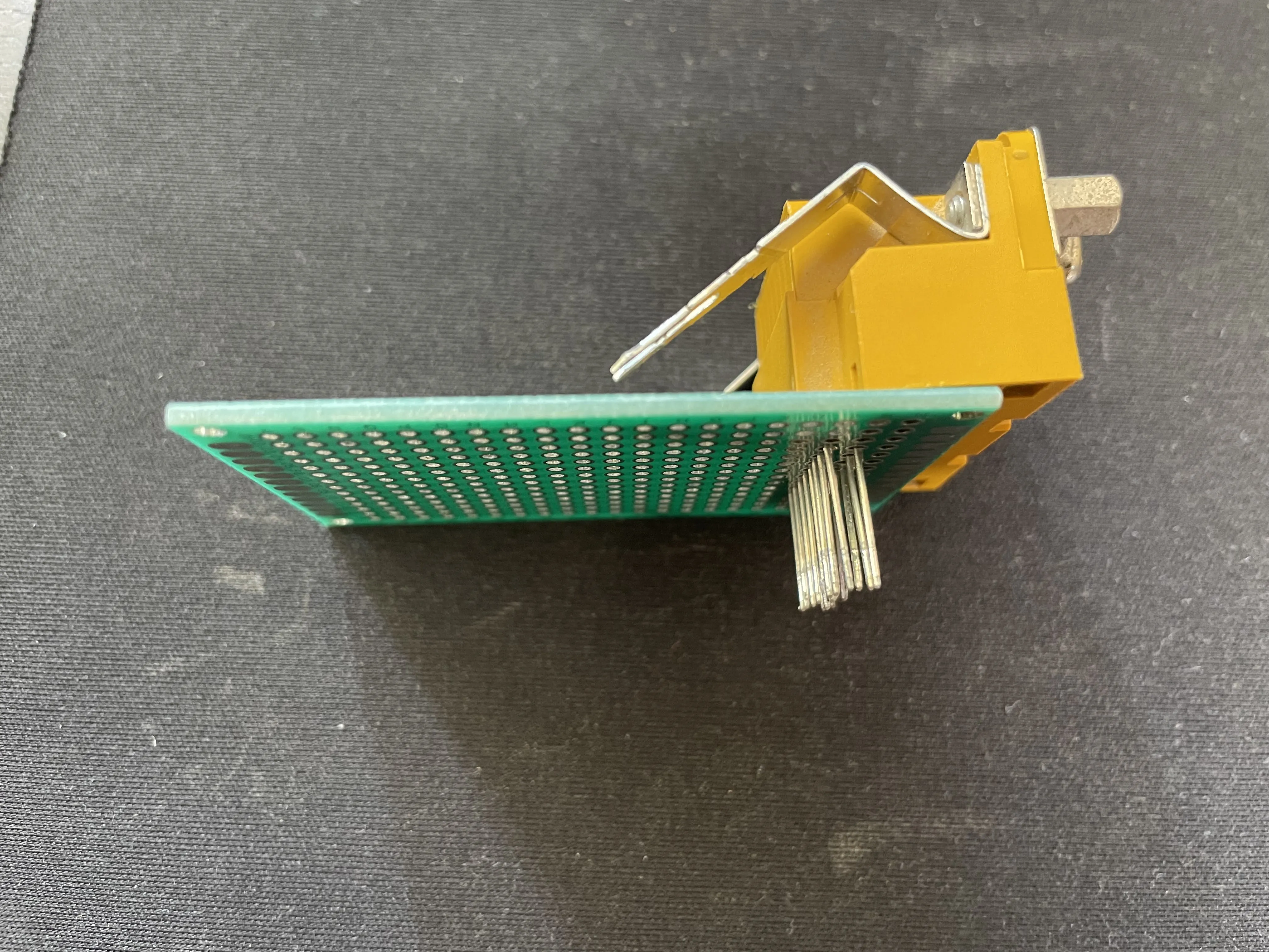
Notice I bent the structural pins that were used originally. I wanted to first test if I could slot the pins in the first place without them getting too mangled, and since this worked, I then marked the PCB and drilled some holes.
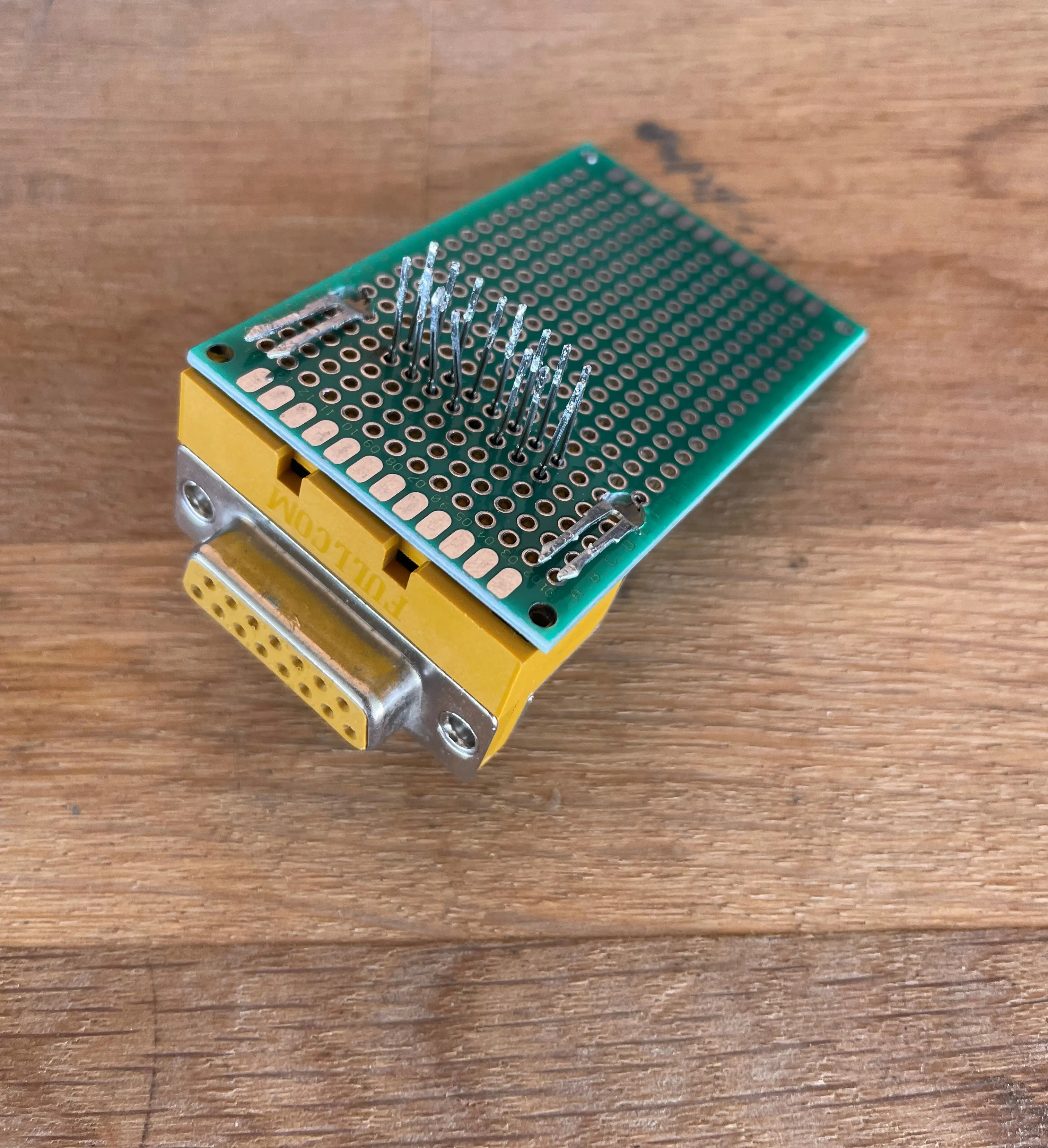
Notice I also bent the structural pins so that they provide more rigidity to the adapter and can be soldered down. This is not ideal but provides more structural rigidity to the board, and takes strain off the data pins when plugging a joystick to the connector.
Arduino
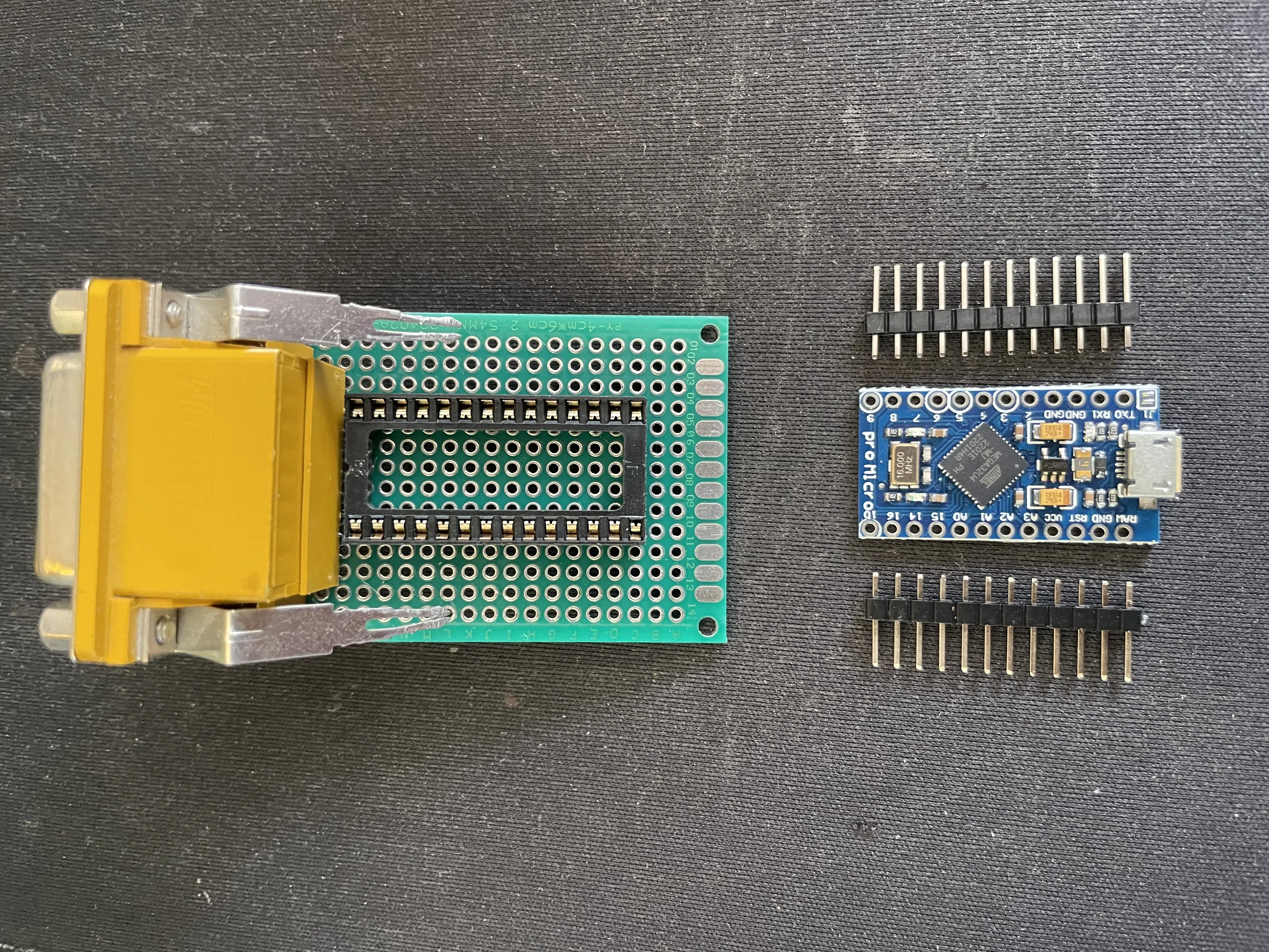
Next up is the arduino. For this, an arduino that uses the ATmega32U4 microcontroller is needed, since this chip handles USB communication internally, as opposed to the commonly used ATmega328P which is typically found on arduino uno boards. The arduino pro micro is a board of small size that uses this microcontroller, and the one used for the original project, so it is the board chosen here.
In order to mount it to the board, I used some socketing connectors so that it can be removed in case it breaks.
Notice that the pins aren’t soldered to the arduino board (yet). This gives us a couple of options since the usual way to solder the pins is to solder the short part of the pins to the board itself, leaving the long part of the pins available for making connection with the socket or other things like breadboards. However, in this case if the pins are soldered to the arduino in this manner, for this socket they will be too long, and there will not be much extra space on the top part of the arduino to connect oscilloscope probes to measure signals. Hence, in my case, I soldered the pins to the arduino the other way, as can be seen in the following picture.
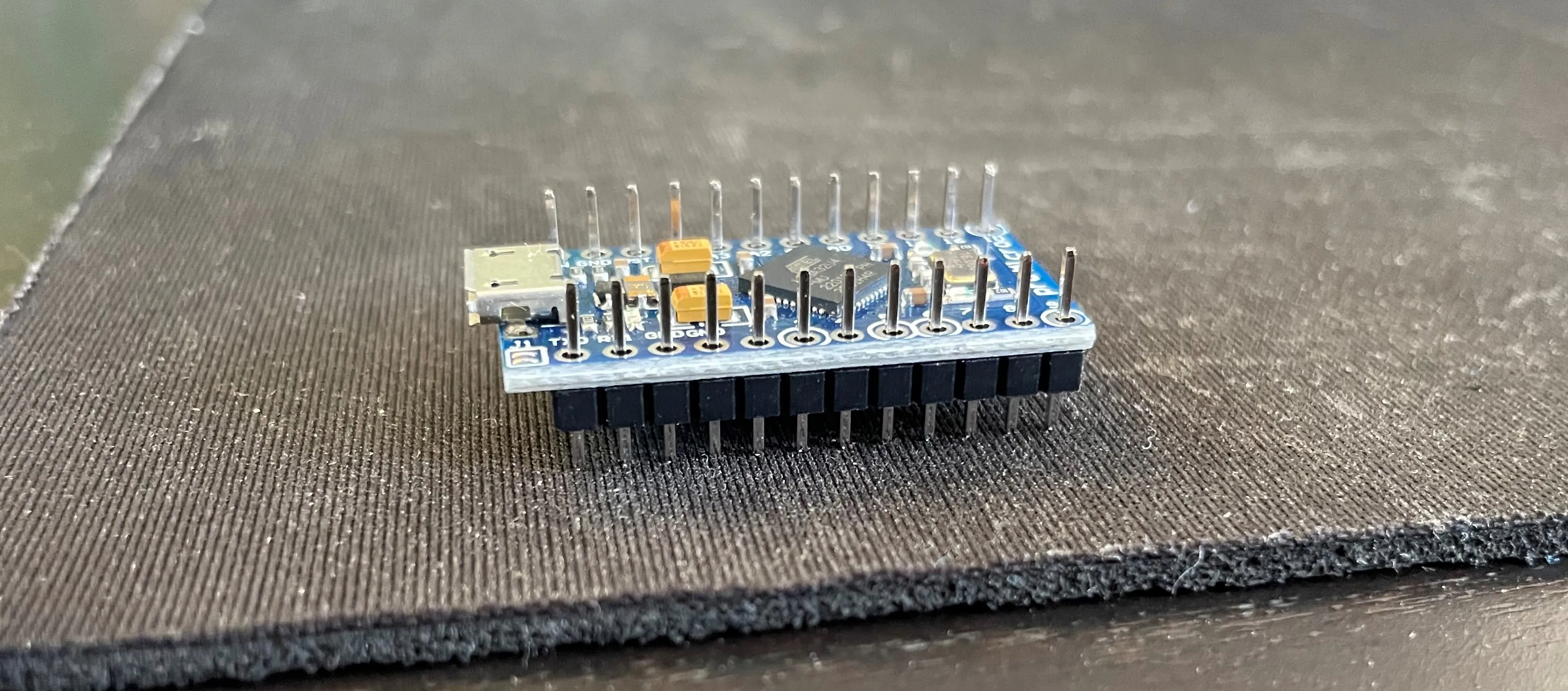
This way the arduino is flush with the socket and there is some extra space to connect probes in case I want to measure signals.
Arranging everything on the board
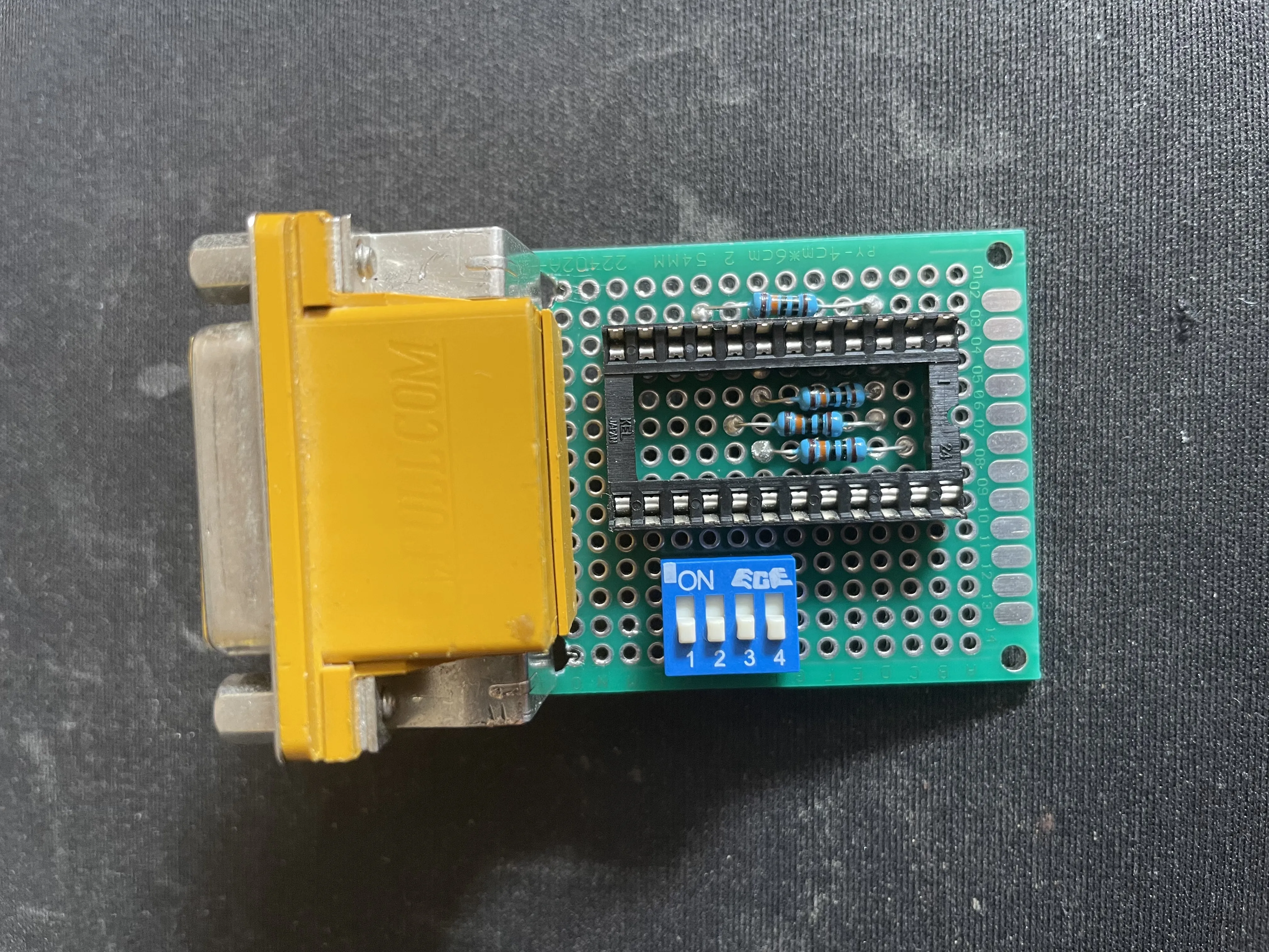
Now it was time to arrange everything on the board before starting to solder it together. This is important because if you start soldering right away, you might realize half way through the job that you did not leave enough space for one of the components and now have to desolder and rearrange components, which is frustrating and time consuming. Apart from the arduino itself, there is also a mode select switch and a few pull down resistors that also need to be added, so I made sure the board would have space for them. The mode select switch is used to provide compatibility with a wide range of gameport joysticks, allowing the arduino to read the input and change the driver code it uses depending on which mode is selected.
First component that I soldered in place was the gameport connector itself, since I already had arranged it so that it would not stick out of the PCB too much and be as centered as possible. The rest of the space on the board will be used for the other components.
As for placing the socket where the arduino will be placed, the idea is to place it in a manner that reduces the amount of connections that are overlapping, so that we can run rails instead of wires, which are less prone to coming loose than wires. The arduino could be placed perpendicular to the gameport connector, but this would make the adapter awkward to use and wires would need to be run from the far side of the arduino to the connector.
Placing it in line with the connector allows rails to be run under the socket and through the outside, and places the micro USB port of the arduino in a more natural position for using the connector. There also needs to be space for 4 resistors on the board, as these are needed for the axes of the joystick, as seen on the schematic.
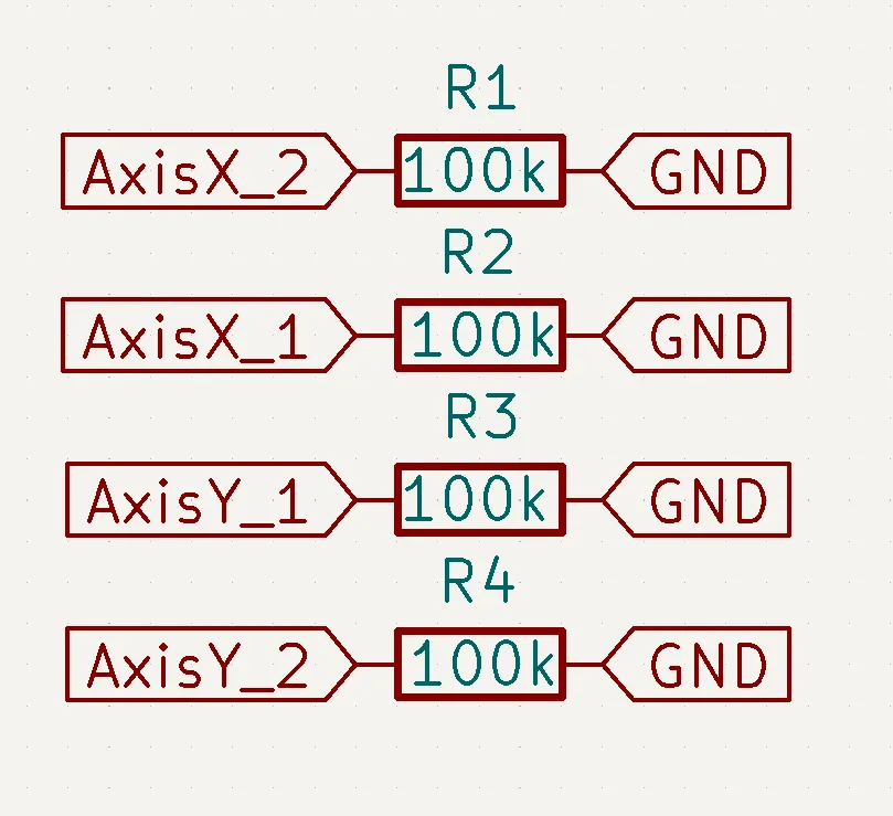
There isn’t an easy way to do this around the socket, but we can actually use the space between the socket and the arduino to fit some resistors. This was made even easier since one end goes to the pins of the arduino and the other to ground, and since the arduino has several ground pins, they came in handy when placing the resistors.
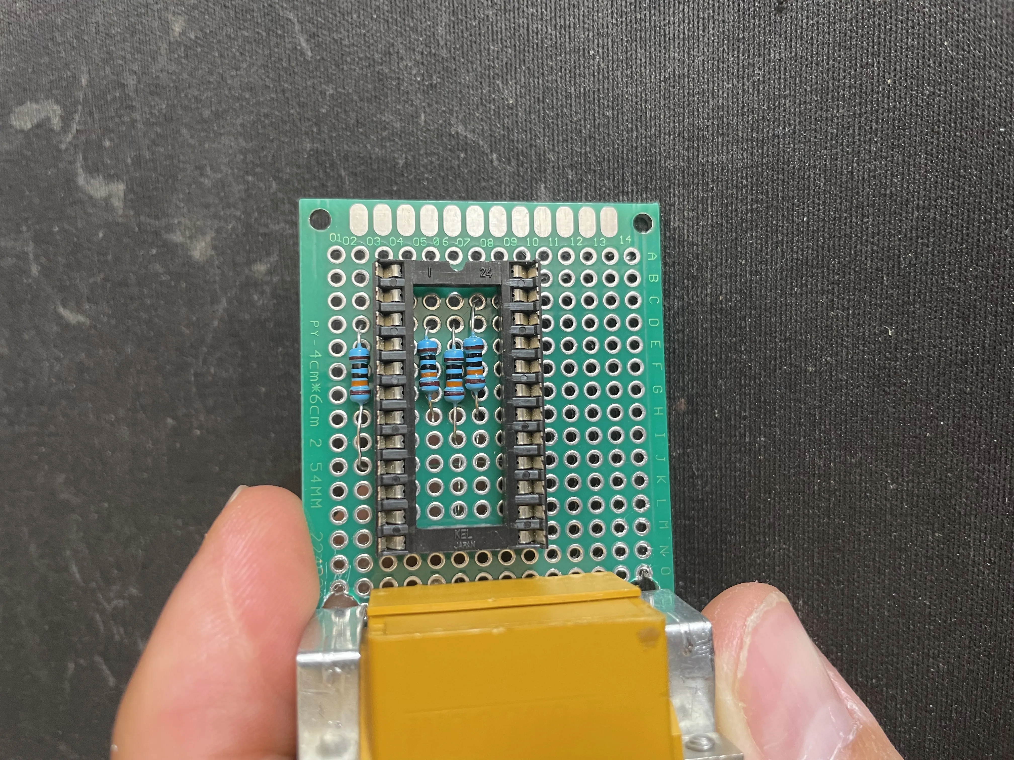
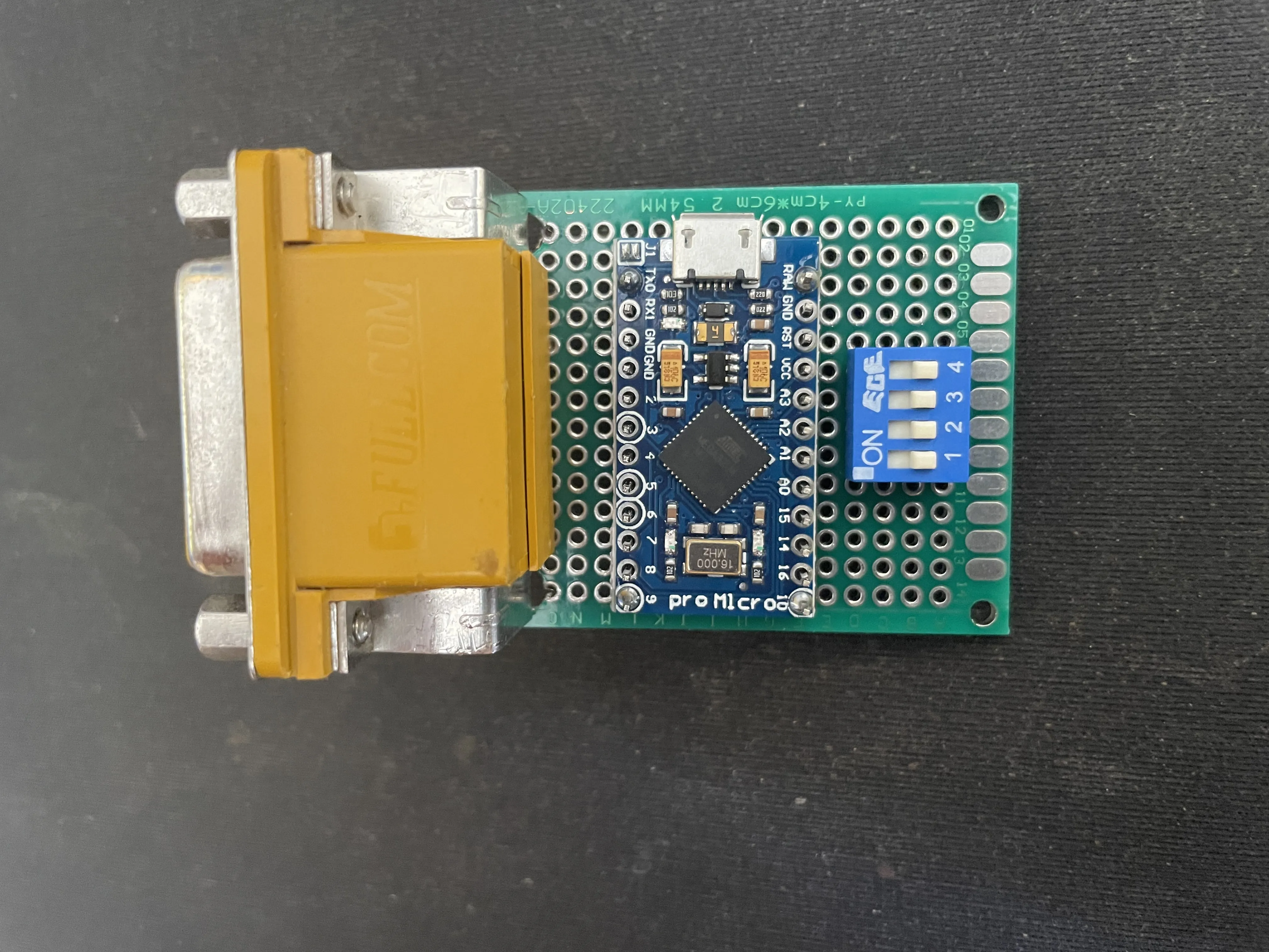
With the space for the resistors covered, I placed the socket off-center on the board to allow for space for the DIP switch and that’s the positioning done! Time to start wiring everything together.
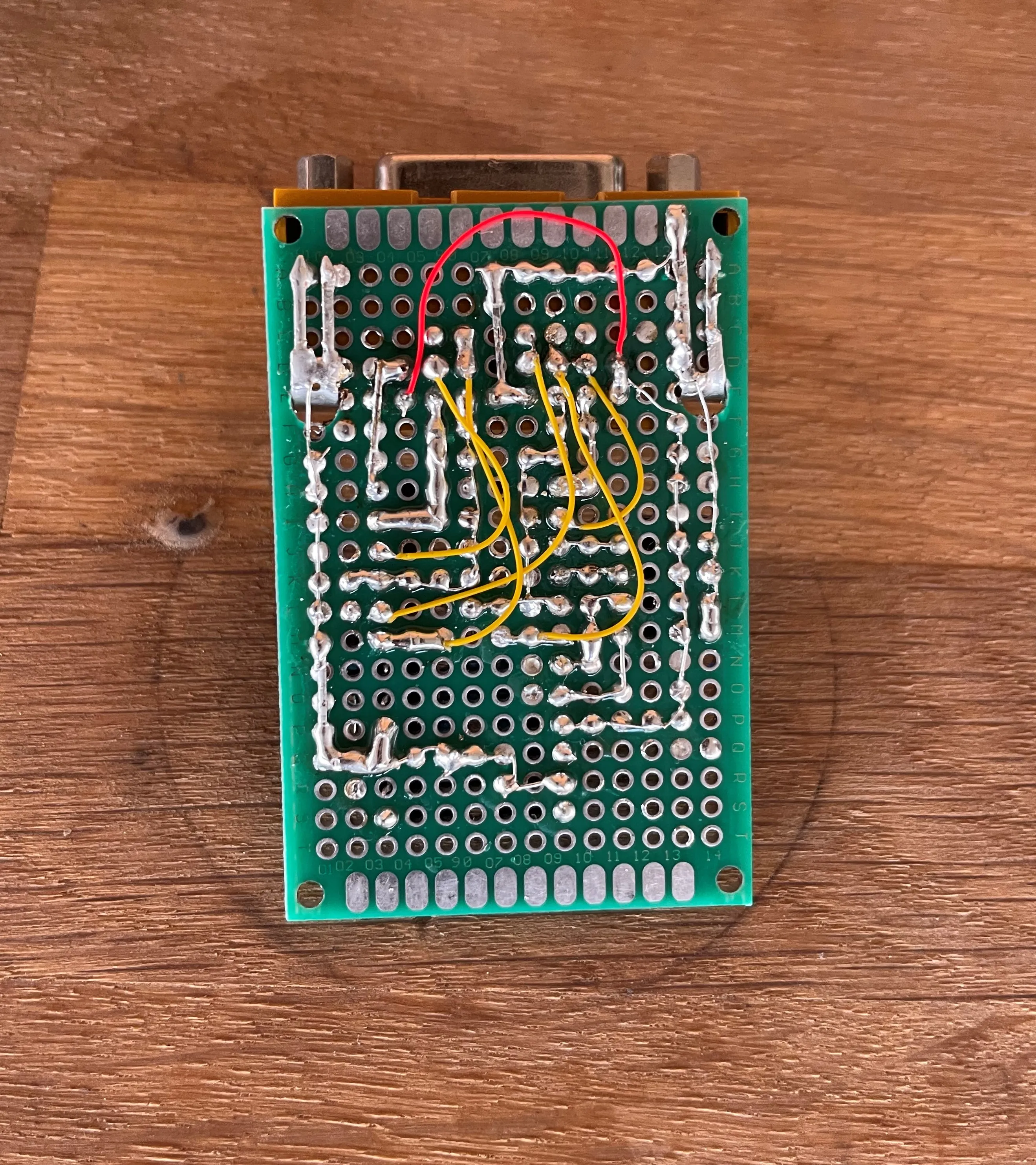
Soldering everything together took about 2h in total. If you look at the final picture from the bottom, you will see the lack of wires used in preference for rails made from bare wire soldered directly to the board. This again helps the connections be more robust and avoids them becoming loose over time. Of course, some wires needed to be used since the connections between some of the pins overlapped.
Programming the arduino and playing games!
To program the arduino, we will use the firmware on the project’s Github repository. Download a project and Navigate to repo_dir/gameport-adapter/firmware/gameport-adapter and open the gameport-adapter.ino file. You need to have the arduino IDE installed.
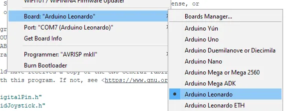
Connect the arduino to your computer. Then select Arduino Leonardo as the board, and the COM port where it is connected to.
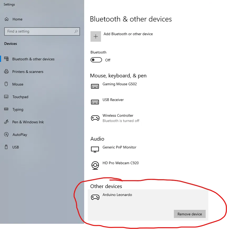
Then all that is left is to upload the code! Once uploaded, in Windows the device will be recognized as a controller.
That’s it! Now it can be used to play DOS games like Star Wars Racer I!
Limitations/Drawbacks of the board
One of the drawbacks of this board is that it does not have a reset switch. This applies both to the arduino itself and the joystick, since they might both need to be reset. The solution is to simply unplug the joystick adapter from the usb end, since this will cut power to both the arduino and the joystick, but it would be a nice feature to have if everything could be reset with a single button.
Wrapping up
This project is a great candidate for a weekend project, since the only major difficulty is soldering the connections together, the rest is done in software that was already kindly made and shared with the world by Necroware. This project would be even faster if you can wait for the PCB to arrive from a manufacturer like JLCPCB, then you only need to solder components to the board and you are done!
As for upgrades/improvements to be made, a case for this adapter would be a great addition to protect the exposed connections in the bottom and avoid the potential of shorts.
Hope it was helpful! Please share this on social media if you know someone that it might help! Links below!