Introduction
This project is a proof of concept to see if I could control an external PC fan connected to my laptop based on the temperature of the CPU. Since my laptop can get quite hot, especially when gaming and under heavy loads, I decided to invest in a laptop cooling pad, but I noticed several drawbacks when using it, mainly that I have to plug and unplug it everytime I want to use or stop using it to turn on its fans.
This got me thinking of a way I could have the fans plugged in all the time, but for them to turn on only when the PC is under heavy load, or the CPU reaches a certain temperature.
In order to see if this would work and was feasible, I came up with a plan, to create a device that gets the laptop’s CPU temperature and turns on and off the fans accordingly.
This requires 2 parts:
- A program or service running on the laptop that can send the temperature of the CPU.
- A microcontroller or similar device that can receive the temperature and act accordingly.
I had an idea to use a thermocouple (temperature sensor) to read the temperature of the CPU, but since this information can be displayed on the computer with applications like OpenHardwareMonitor and MSI Afterburner, then ideally the laptop would send this information to the microcontroller, since it would be the temperature of the CPU as reported by the temperature sensors on the chip.
Program implementation
The requirements I set for the software running on the host computer is simple: Every 1 second it sends the temperature information to the microcontroller over a USB connection and runs in the background. Since this is more of a proof of concept I kept the requirements simple.
Personally, my laptop is running Windows 11, so the software would need to be able to run in the background on this OS. I began exploring several options and eventually settled on a .NET Framework application that would compile into a Windows service. This service could then be started and stopped with a simple command, and could even be set to run on boot.
The next piece is to actually get the temperature of the CPU. For this, I used the OpenHardwareMonitor .dll file and added it to the Visual Studio project as a reference. A .dll file is a dynamic link library. In practical terms, this file contains all the functions that the OpenHardwareMonitor software provides on their github repository. Within these are functions to get the temperature of the CPU.
The last requirement is that it communicates with the microcontroller. I chose to use an Arduino since it is what I had at hand and is easy to program. I used the LattePanda Development support github as help, since it contains this file that implements helper functions to send information easily to the Arduino. I modified this file to remove 2-way communication, only leaving the functionality to send data to the Arduino but not receive. This was due to the program consuming a high amount of CPU waiting for information from the Arduino, when it is not necesary for this project. In the future, I plan to change this code to use interruptions instead of polling to improve performance and enable the Arduino to send data back to the PC.
The functions provided by this file rely on the Arduino running Firmata firmware. Firmata is a protocol that makes it easier for a computer to communicate with a microcontroller. To install it on the Arduino IDE, check the instructions on their github page.
You can check out my project repository and use the code yourself! The instructions on how to run it can also be found there.
Arduino side
For the Arduino side, we need to upload code that will understand the Firmata protocol, as mentioned before. I have implemented a slightly modified version of some of their example code to make the program a bit leaner, and remove functionality that is not necesary for this to work. Again, you can find the code and instructions on my project repository. It essentially consists of compiling and uploading the Arduino sketch to the board.
Wiring it all up
NOTE! Be careful when wiring this up since if you connect things wrong there is a chance to break your Arduino, especially if you connect the 12V positive lead of the supply for the fan with yout positive 5V from the Arduino!
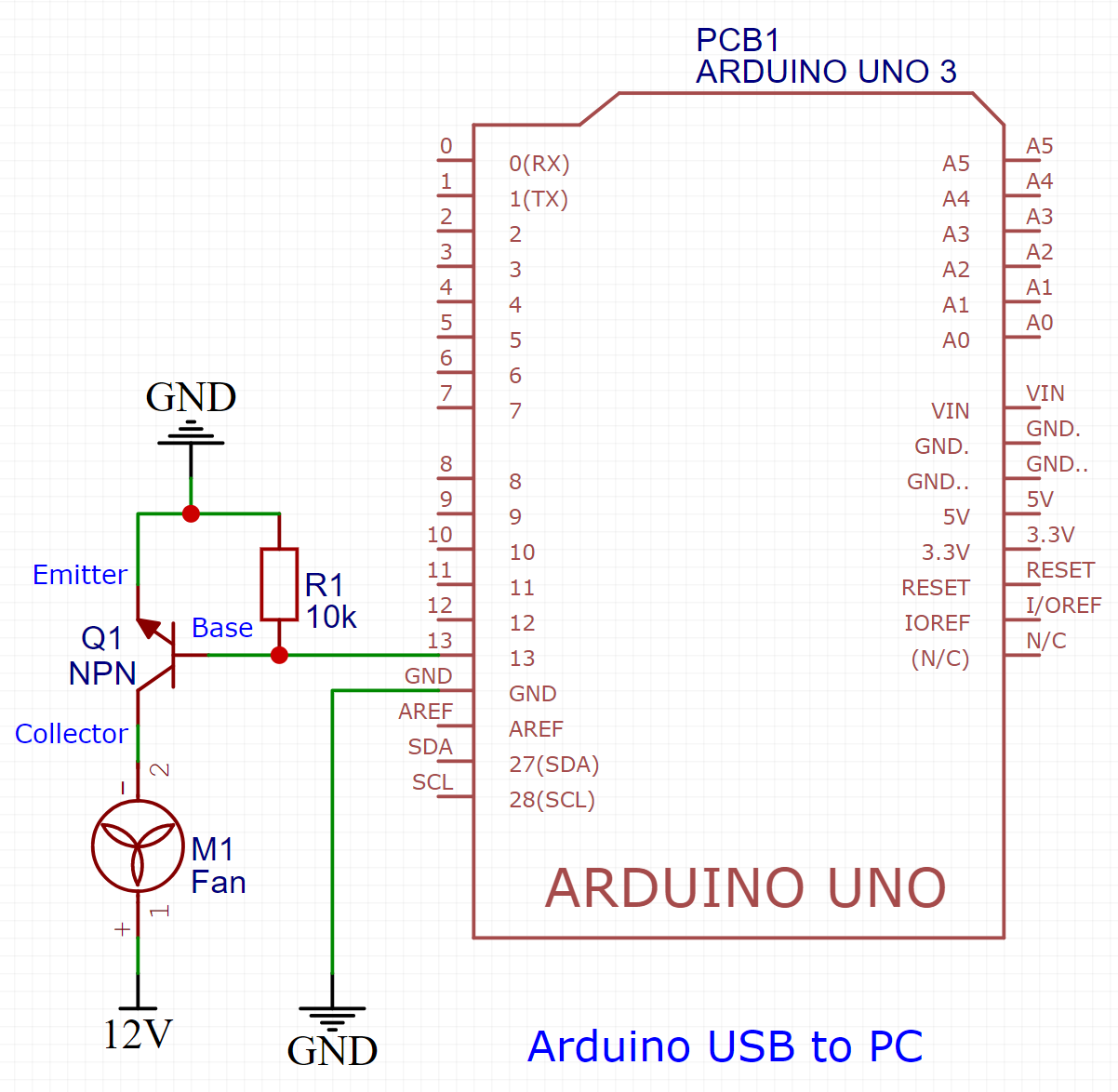
The circuit is fairly simple. The control pin from the Arduino, in this case pin 13, is connected to the base of an NPN transistor. This will either allow or stop current to flow through the other 2 pins, the collector-emitter path. Also needed here is a pulldown resistor to ensure that when the control pin of the arduino is off, the signal gets pulled to ground and prevents the NPN from allowing current to flow.
Connect the collector to the negative side of the fan, and the emitter to ground. The positive side of the fan gets connected to the positive side of the 12V supply. Make sure you connect the 12V supply and the arduino grounds together, but NOT the positive 12V of the supply and the positive 5V of the Arduino. This will break your Arduino!
Drawbacks and limitations
There are several drawbacks to the system in it’s current state, mainly:
- The temperature thresholds cannot be dynamically selected once the program has started. If you want to change it you have to change it in code and recompile the Windows background task.
- No hotplugging of the arduino. In order for the service to start, the Arduino needs to be plugged in. If it isn’t the service will fail to start, and if you unplug it once it is started, it will exit.
- No 2 way communication. The Arduino currently can only receive info.
- Binary control of the fan, either on or off, no speeds based on the temperature.
- Current fan used needs an external 12V PSU.
Obviously since this was mainly a test, there are features that were not implemented. In the future I want to integrate this into the cooling pad mentioned and add some improvements that would make this project more user friendly.
Hope it was helpful! Please share this on social media if you know someone that it might help! Links below!